Arduino RGB LED Control Project
This project demonstrates how to control an RGB LED using three buttons with an Arduino. One button toggles an auto-cycling mode, while the other two buttons allow manual color selection.
Components Required
- Arduino Uno
- RGB LED
- 3 Push Buttons
- 3 Resistors (220Ω for RGB LED)
- 3 Resistors (10kΩ for buttons)
- Breadboard
- Jumper Wires
- USB Cable
- Zero PCB
Circuit Diagram
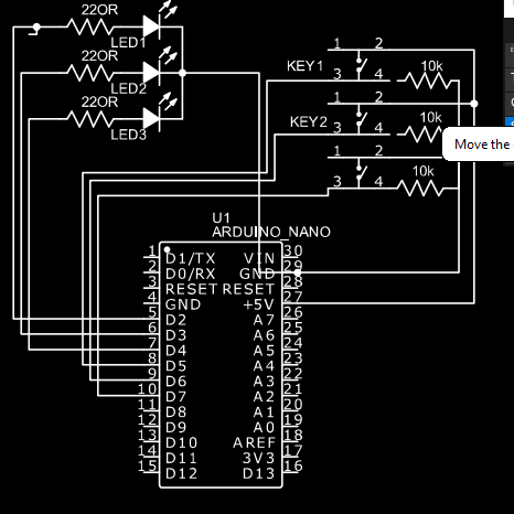
Replace the above image with the actual circuit diagram of your project.
Zero PCB Assembly
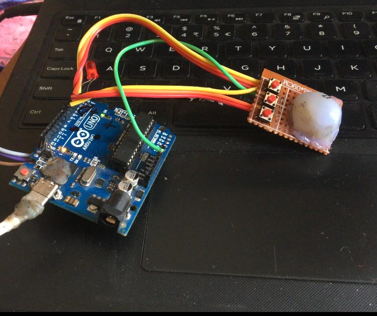
Replace the above image with a photo of your Zero PCB assembly.
Arduino Code
  // Pin Definitions
  const int redPin = D1;
  const int greenPin = D2;
  const int bluePin = D3;
  const int autoModeButton = D4;
  const int colorUpButton = D5;
  const int colorDownButton = D6;

  // Variables
  bool autoMode = false;
  int currentColor = 0; // 0: Red, 1: Green, 2: Blue
  unsigned long previousMillis = 0;
  const long interval = 1000; // Auto mode color change interval

  void setup() {
    // Set pin modes
    pinMode(redPin, OUTPUT);
    pinMode(greenPin, OUTPUT);
    pinMode(bluePin, OUTPUT);
    pinMode(autoModeButton, INPUT);
    pinMode(colorUpButton, INPUT);
    pinMode(colorDownButton, INPUT);

    // Initialize LED to off
    setColor(0, 0, 0);
  }

  void loop() {
    // Check if auto mode button is pressed
    if (digitalRead(autoModeButton) == HIGH) {
      delay(200); // Debounce delay
      autoMode = !autoMode; // Toggle auto mode
      while (digitalRead(autoModeButton) == HIGH); // Wait for button release
    }

    if (autoMode) {
      // Auto mode: Cycle through colors
      unsigned long currentMillis = millis();
      if (currentMillis - previousMillis >= interval) {
        previousMillis = currentMillis;
        currentColor = (currentColor + 1) % 3; // Cycle through 0, 1, 2
        setColor(currentColor);
      }
    } else {
      // Manual mode: Use buttons to change colors
      if (digitalRead(colorUpButton) == HIGH) {
        delay(200); // Debounce delay
        currentColor = (currentColor + 1) % 3; // Next color
        setColor(currentColor);
        while (digitalRead(colorUpButton) == HIGH); // Wait for button release
      }
      if (digitalRead(colorDownButton) == HIGH) {
        delay(200); // Debounce delay
        currentColor = (currentColor - 1 + 3) % 3; // Previous color
        setColor(currentColor);
        while (digitalRead(colorDownButton) == HIGH); // Wait for button release
      }
    }
  }

  // Function to set RGB LED color based on currentColor
  void setColor(int color) {
    switch (color) {
      case 0: // Red
        digitalWrite(redPin, HIGH);
        digitalWrite(greenPin, LOW);
        digitalWrite(bluePin, LOW);
        break;
      case 1: // Green
        digitalWrite(redPin, LOW);
        digitalWrite(greenPin, HIGH);
        digitalWrite(bluePin, LOW);
        break;
      case 2: // Blue
        digitalWrite(redPin, LOW);
        digitalWrite(greenPin, LOW);
        digitalWrite(bluePin, HIGH);
        break;
    }
  }
Project Video
Conclusion
This project demonstrates how to control an RGB LED using three buttons with an Arduino. One button toggles an auto-cycling mode, while the other two buttons allow manual color selection. Using a Zero PCB makes the project compact and durable.